


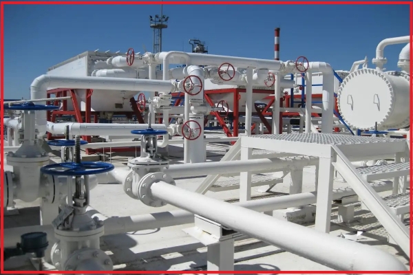
Industrial Valve Installation Guide: Proper Techniques and Important Considerations
Pipeline Valve Installation
1. Valve Installation Position
The valve installation position must be convenient for operation. Even if installation is temporarily difficult, long-term operation and maintenance should still be considered. The valve handwheel should ideally be positioned at chest height (usually about 1.2 meters above the operating floor) to make opening and closing easier.
The handwheel of floor-mounted valves should face upward and should not be tilted to avoid difficult operation. For valves installed close to walls, enough space should be left for operators to work comfortably.
Overhead operation should be avoided, especially when handling acidic, alkaline, or toxic media, as it is very dangerous.
Gate valves must not be installed upside down (with the handwheel facing downward), because the medium may remain inside the bonnet for a long time, causing corrosion of the valve stem and failing to meet certain process requirements. In addition, replacing the packing becomes inconvenient.
When installing gate valves, they should not be buried underground because the exposed valve stem can easily corrode due to moisture.
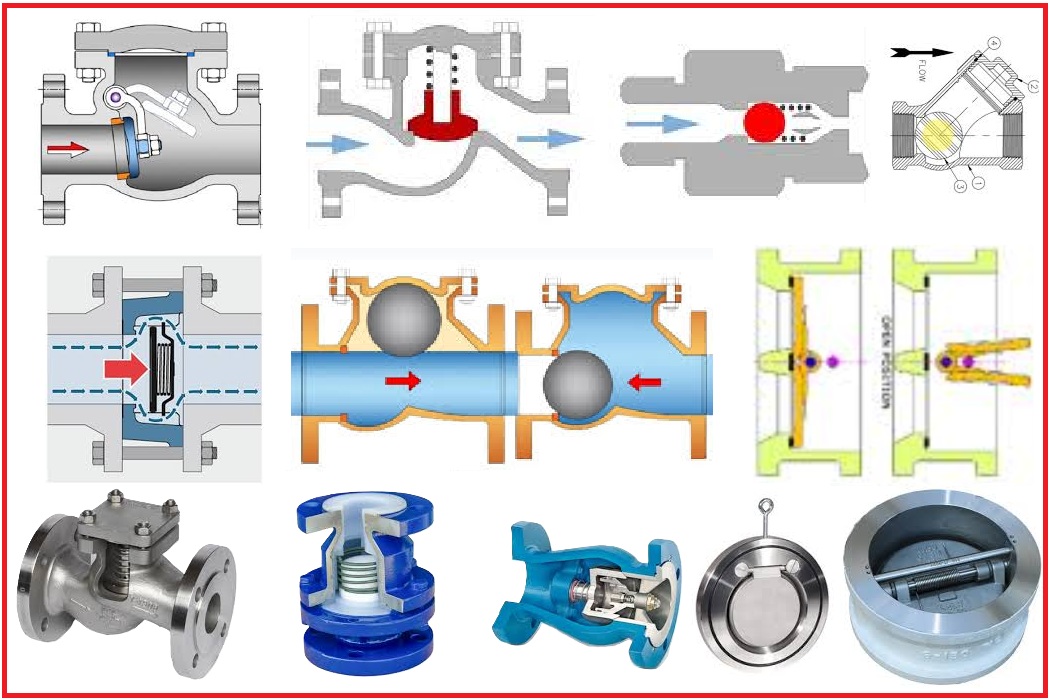
Lift check valves must be installed with the valve disc in a vertical position to ensure smooth movement. Swing check valves must be installed with the pin shaft in a horizontal position for proper operation.
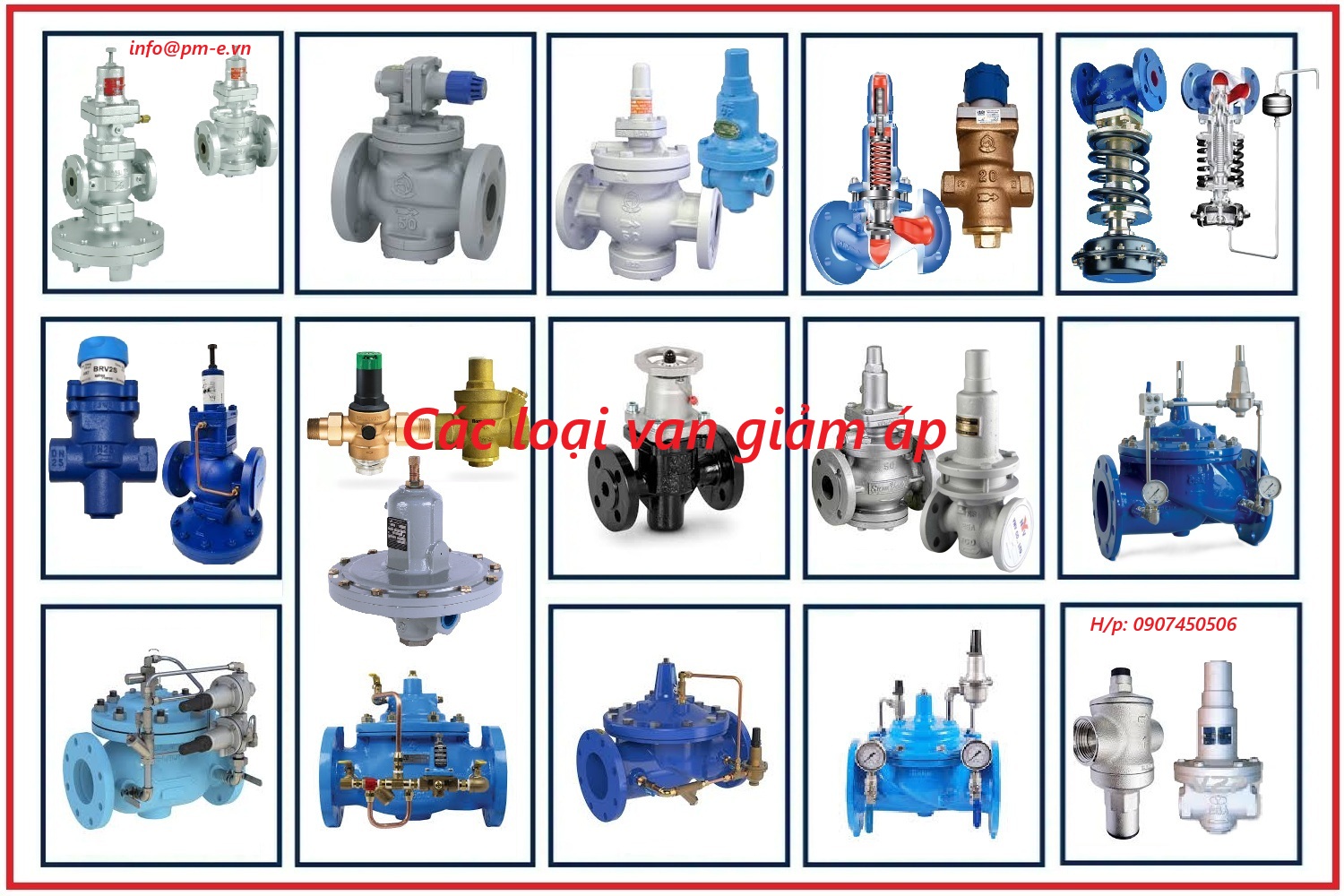
Pressure reducing valves must be installed vertically on horizontal pipelines and should not be tilted.
2. Construction Work
Careful handling is required during installation and construction. Avoid heavy impacts on valves made from brittle materials.
Before Installation
- Carefully check the model and specifications of all valves to ensure they meet design requirements.
- Inspect the condition of the packing, gland bolts, valve stem, and valve disc to ensure proper operation.
- Clean all debris and impurities inside the valve.
Installation Process
- When lifting the valve, do not attach ropes to the handwheel or valve stem to prevent damage.
- Pipelines connected to the valve must be thoroughly cleaned.
- Compressed air can be used to remove welding slag, sand, dust, and other impurities.
- When installing threaded valves, thread sealing material should be wrapped around the pipe thread, not inside the valve body.
- For flanged valves, bolts must be tightened evenly and symmetrically.
3. Protective Measures
Some valves require insulation or cold protection.
- Valves used in hot steam systems should be insulated.
- Valves exposed to cold environments require anti-freezing protection.
- Common insulation materials include glass wool, asbestos, and perlite.
- Cold insulation materials include foam, plastic, and cork.
4. Bypass Lines and Measuring Instruments
Some valves require bypass lines and pressure gauges for easier maintenance and operation.
5. Packing Replacement
Many stored valves use packing materials unsuitable for the operating medium and therefore require replacement.
When replacing packing:
- Compress the packing ring by ring.
- Stagger the joints by 120°–180°.
- Do not over-tighten to avoid valve stem wear.
Common packing materials include:
- PTFE (Teflon) gasket
- Nitrile rubber gasket
- Fluororubber gasket
- Nylon gasket
Valve Pressure Testing
1. Strength Test
The strength test is carried out with the valve open to check for body leakage.
- Test pressure = 1.5 times the nominal pressure.
- Test duration ≥ 5 minutes.
- No leakage is permitted.
2. Tightness Test
The tightness test is performed with the valve fully closed to check the sealing surface.
The valve is considered qualified if no leakage occurs at the sealing surface.
General Rules for Valve Installation
- Valve installation must not obstruct operation or maintenance.
- Valves on horizontal pipelines should have the valve stem facing upward.
- Valves on vertical pipelines should allow convenient operation.
- The minimum spacing between handwheels should be 100 mm.
- Heavy valves require separate supports.
- The arrow on the valve body must match the flow direction of the medium.
Important Valve Installation Notes
- Cast iron valve bodies are brittle and must not be subjected to heavy impact.
- Valves must not be buried directly underground.
- Flange bolts must be tightened diagonally and evenly.
- Valves should remain closed during installation.
- For threaded valves installed near walls, the handwheel may need to be removed during installation.
14 Common Valve Installation Mistakes and Solutions
1. No Material Quality Certification
Consequence: Poor project quality.
Solution: Use only certified materials.
2. Failure to Test Valves Before Installation
Consequence: Leakage or valve jamming during operation.
Solution: Perform strength and tightness tests before installation.
3. Incorrect Valve Selection
Consequence: Improper valve operation.
Solution: Select valves according to design specifications.
4. Incorrect Valve Installation Direction
Consequence: Valve malfunction or leakage.
Solution: Install according to the flow direction arrow.
5. Incorrect Flange Used for Butterfly Valves
Consequence: Valve damage or difficult operation.
Solution: Use the correct flange size.
6. Failure to Reserve Technical Openings
Consequence: Structural demolition required.
Solution: Prepare openings and embedded parts in advance.
7. Poor Welding Technique
Consequence: Weak welds and leakage.
Solution: Weld according to proper standards and clearances.
8. Installing Pipes in Unstable Soil
Consequence: Pipe settlement or breakage.
Solution: Reinforce the foundation before installation.
9. Using Poor-Quality Expansion Bolts
Consequence: Loose or collapsed supports.
Solution: Use standard-quality expansion bolts.
10. Incorrect Flange Gasket Selection
Consequence: Leakage.
Solution: Select gaskets suitable for the operating environment.
11. Incomplete Pressure Inspection
Consequence: System leakage after operation.
Solution: Thoroughly inspect the entire system.
12. Failure to Perform Drainage Pipe Leak Testing
Consequence: Hidden leakage.
Solution: Conduct leak testing before concealment.
13. Improper Pipeline Flushing
Consequence: System blockage.
Solution: Flush at the required flow rate.
14. Pressure Testing at Freezing Temperatures
Consequence: Freezing and cracking.
Solution: Perform testing at positive temperatures or use compressed air.
Common Types of Valves
Gate Valve
- Used for fully opening or closing flow. Not suitable for flow regulation.
.jpg)
Globe Valve
- Used for flow regulation. The flow direction must be from bottom to top during installation.
%20-%20Copy.jpg)
Check Valve
- Prevents backflow and must be installed in the correct flow direction.
Pressure Reducing Valve
- Automatically reduces inlet pressure to the required level.
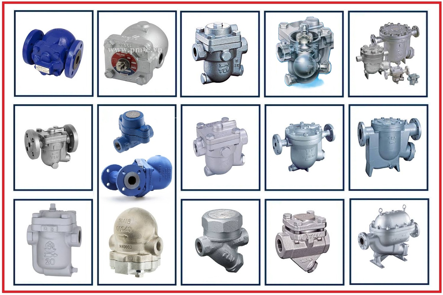
Steam Trap
- Automatically discharges condensate while retaining steam.
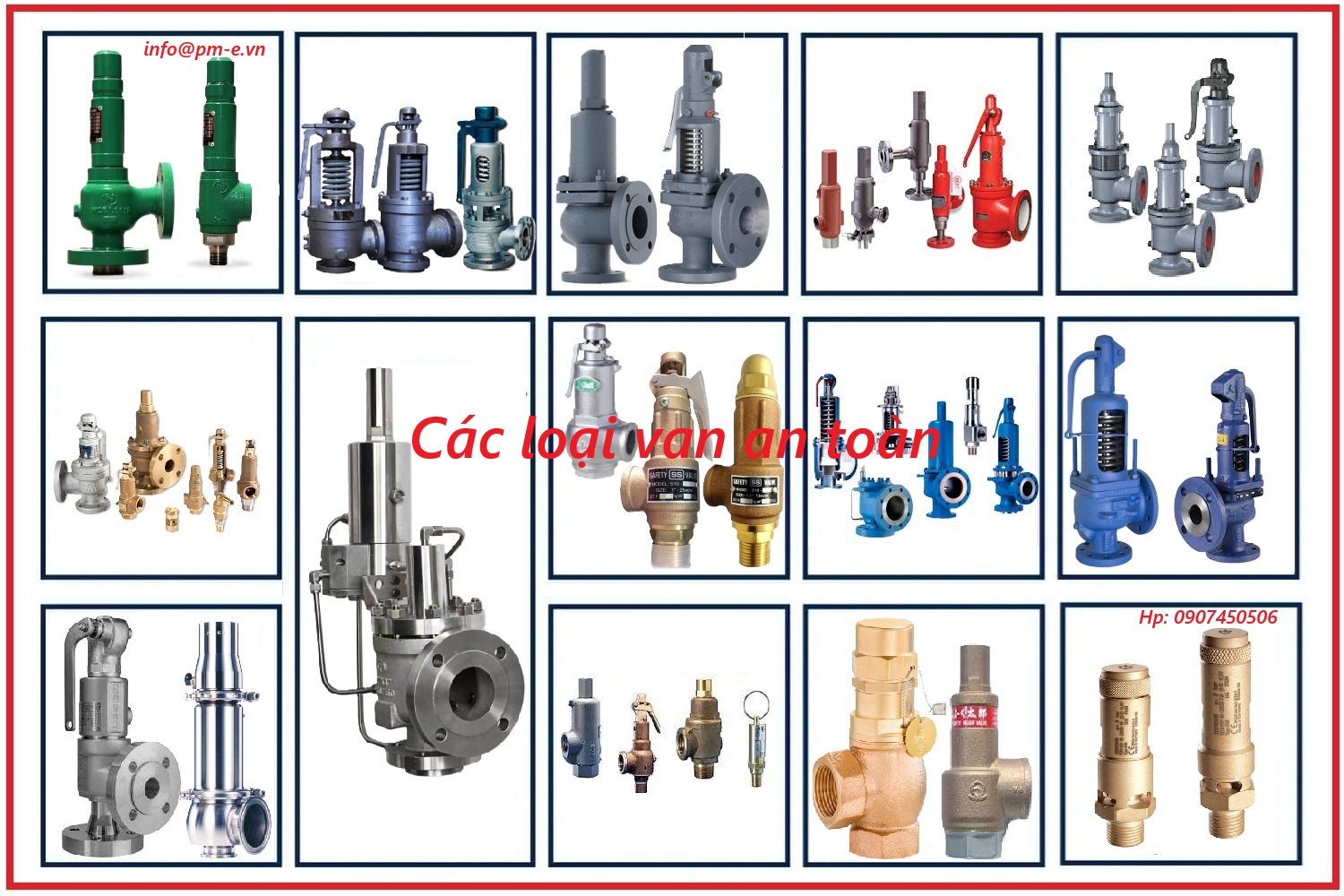
Safety Valve
- Protects the system when pressure exceeds the allowable limit.
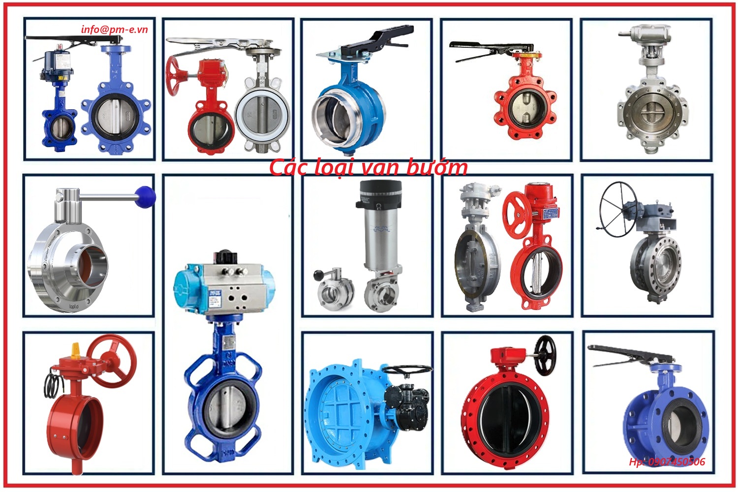
Butterfly Valve
- Used for fully opening or closing the flow. It is not suitable for flow regulation.
Control Valve
- Used to control the opening and closing of flow by electric or pneumatic actuation. Suitable for regulating flow rate, controlling pressure, temperature, and flow volume.
.jpg)
Knife Valve
-
Used for opening and closing flow with a cutting function for media such as paper pulp, slurry, and other soft solid materials. It is not suitable for flow regulation.
%20l%C3%A0%20g%C3%AC.jpg)
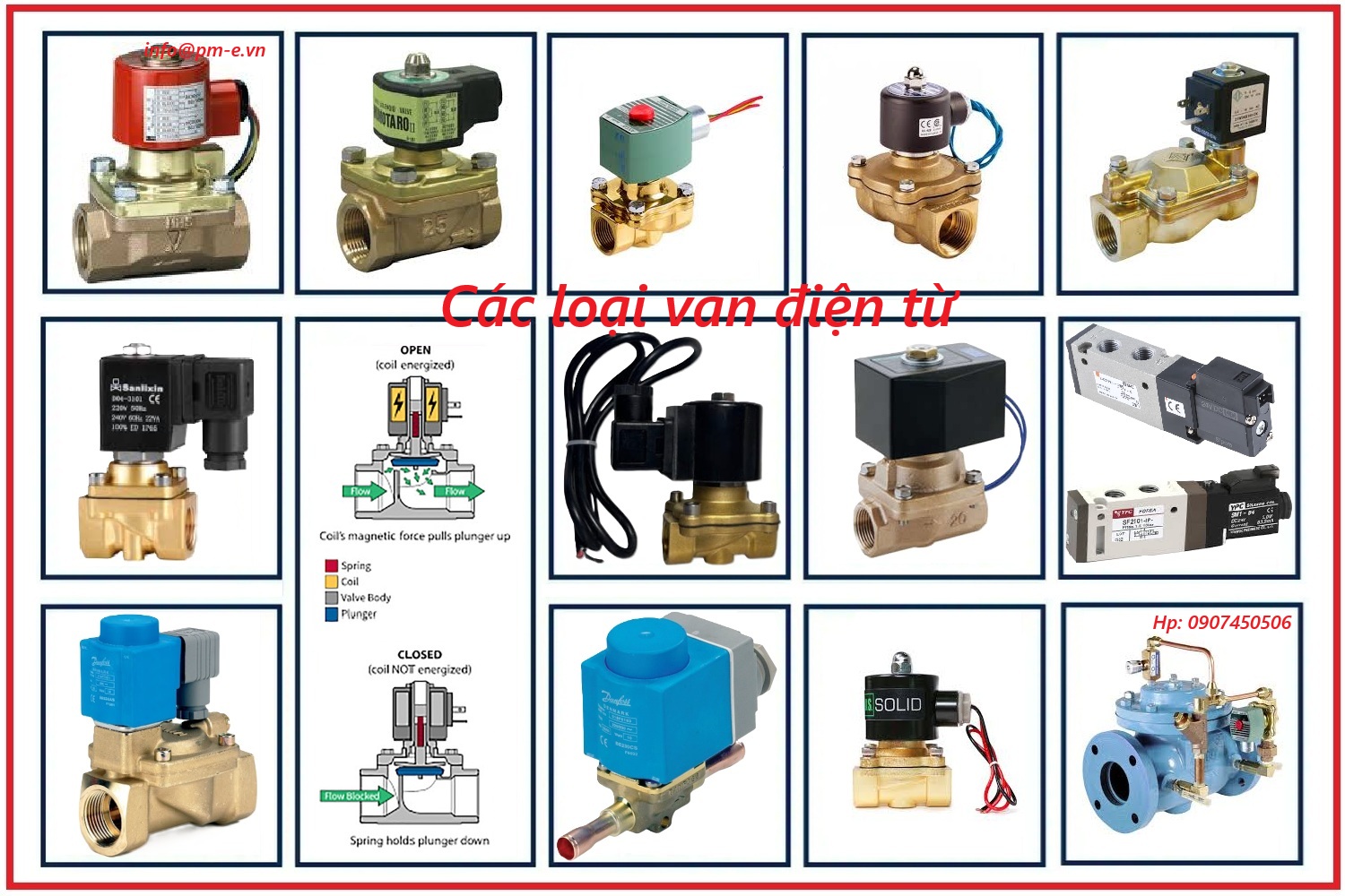
Solenoid Valve
- Used for quickly and fully opening or closing the flow by electric actuation. It is not suitable for flow regulation.
Common Valve Problems
Packing Leakage
Causes:
- Incorrect packing installation
- Worn valve stem
- Aging packing material
Solutions:
- Replace packing material
- Repair or replace the valve stem
Difficult Valve Operation
Causes:
- Rust
- Dirt accumulation
- Bent valve stem
Solutions:
- Clean the valve
- Replace damaged components
Sealing Surface Leakage
Causes:
- Worn sealing surface
- Foreign particles
- Misaligned valve disc
Solutions:
- Regrind the sealing surface
- Remove debris
- Adjust or replace the valve disc
Related News
Installation Guide For Deluge Valves
25/03/2026
Deluge valves are critical components in fire protection systems, especially in high-risk areas or large-scale sprinkler networks. These valves allow rapid water discharge throughout the system upon receiving a fire signal, effectively protecting property and personnel.
Industrial Valve Installation Guide
10/05/2026
Learn the correct industrial valve installation procedures, pressure testing standards, construction precautions, and common installation mistakes in industrial piping systems.
KSPC - Installation, Operation and Maintenance Manual
20/11/2025
Installation, Operation and Maintenance Manual for 1. BREATHER VALVE. 2. EMERGENCY VENT COVER. 3. FLAME ARRESTER. 4. GAUGE HATCH & SLOT DIPPING DEVICES. 5. N2 BLANKETING VALVE. 6. SAMPLING SYSTEM TYPE MBS-A2. 7. KSEPW MODEL - EMERGENCY VENT COVER.


VINVAL J61Y-2500LB Globe Valve DN40 (1.1/2") | Class 2500#, BW, ASTM A182 F11
24,000,000 d 26,666,667 d

VINVAL Z61Y-800LB Gate Valve DN25 (1") | Class 800#, Socket Weld (SW)
1,244,430 d 1,464,040 d

VINVAL J61Y-2500LB Globe Valve DN25 (1") | Class 2500#, ASTM A182 F11, BW
11,200,000 d 12,444,444 d

VINVAL Z61Y-800LB Gate Valve DN20 (3/4") | Class 800#, Socket Weld (SW)
829,610 d 976,010 d

VINVAL J61Y-800LB Globe Valve DN25 (1") | Class 800#, Socket Weld, Full Stellite Trim
1,244,430 d 1,464,035 d
About us

PHUC MINH ENGINEERING CO., LTD
Head Office: 92/38, No.12 St, Quarter 18, Binh Hung Hoa Ward, Ho Chi Minh City, Vietnam.
Tax Code: 0314405007
Tel: +842835352125
Fax: +842835350254
Email: info@pm-e.vn
Website: www.pm-e.vn
Quang Ngai Branch:
Address: 123/4 Vo Thi Sau, Chanh Lo, Quang Ngai, 840255, Vietnam
- Policies and regulations
- Payments
- Shipping and forwarding
- Warranty Policy
- Complaint handling process
- Exchanges and refunds
- Privacy Policy
Return Policy
Social network

.png)


Copyright © 20017 Copyright by Phuc Minh Technology Co., Ltd